
I had a problem with my keyboard (Mysterium PCB mod produced by my friends over at catgirl.software) where the A key would only work sometimes. It would work sporatically; when I press down on the key there is no guarantee that anything is going to print. If I hold it down, it would maybe burst print some few seconds, then stop, then start again after some times.
That made things super annoying because I really liked this keyboard and having a temperamental A key meant that sometimes I can't move left in a videogame (not that big a deal), and it breaks my typing flow (very HUGE deal).
The keyboard is relatively new, and I soldered the switches (and everything else!) myself, so it was unlikely to be a problem with the switches being worn out, or some issue with a blob of solder being not where it is supposed to be.
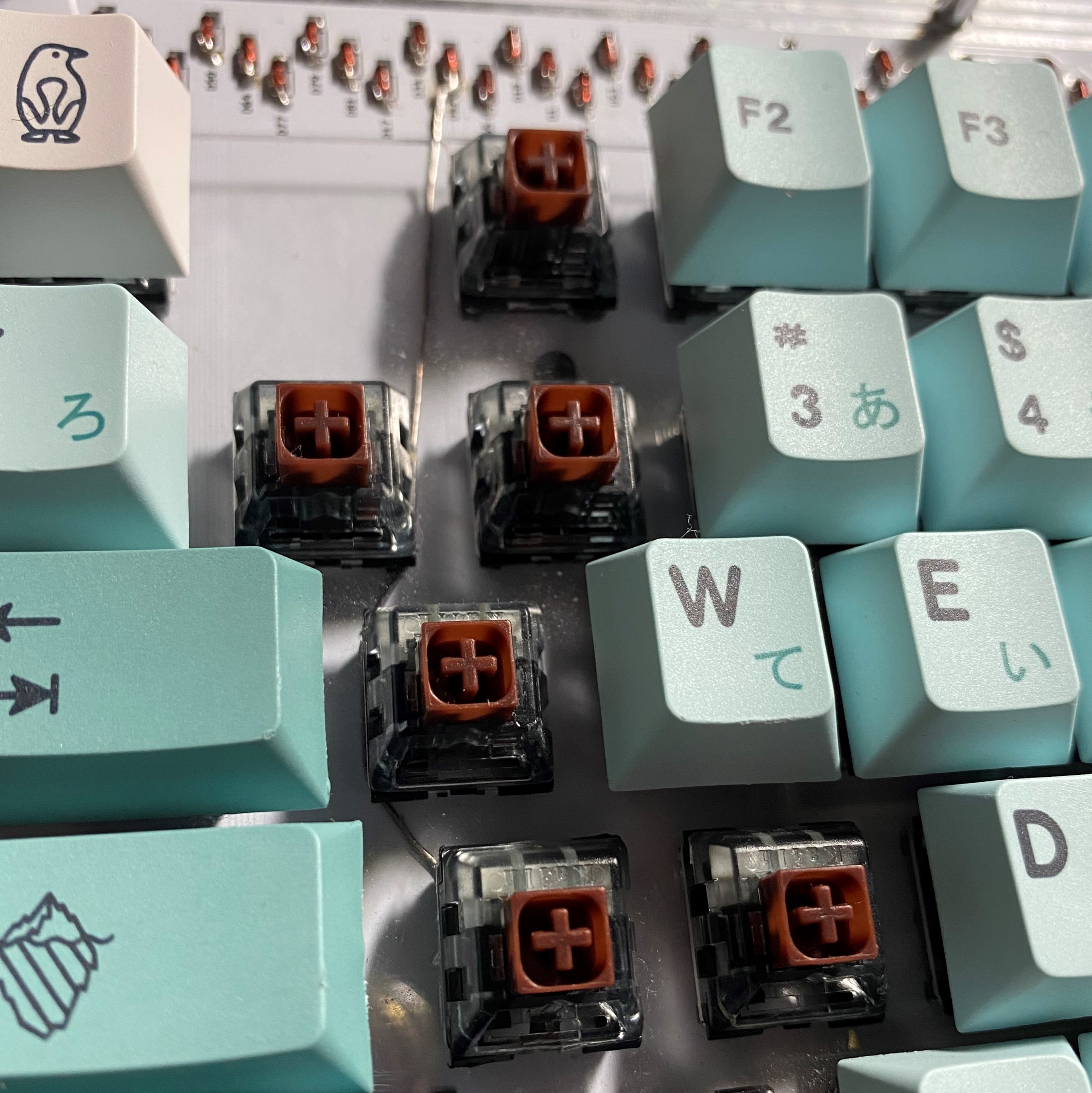
Seeing as this keyboard has all it's components obfuscated behind one layer of acrylic plate held on to the PCB with screws, I decided to take it apart (unscrew the screws).
I took my multimeter and measured the voltage across the two pins of the A key. 0.20V.
Then I did the same to the other keys around it. 0.70V. Oh.
It looks like the incoming voltage to this key is lower than the others. Since the keyboard is expecting a significantly higher current to flow through when I press the key, the press of the A key does not get registered, and nothing prints.
The voltage at A actually fluctuates between 0.65V to 0.10V, but it tends to stay around the low side. This is why the key only works sometimes and not the others. It only works when the voltage is above a certain threshold.
To fix this issue, I am going to have to trace back to where the current is coming from (one of the diodes), then run a line directly from the business end of the diode to the voltage-in pin of the switch. This is assuming that the diode is functioning as expected, which, it should, because I tested every single one of the 93 before I soldered them.)
Thanks to the continuity test on the multimeter (it beeps when the two probes are in the same circuit, got to be my favourite multimeter function), I was able to identify that diode D52 is in the same circuit as the voltage-in pin of the A key. I also saw that more than enough current is coming from D52, so the problem is most likely to be caused by an issue with the subsurface tracks in the PCB.
I desoldered the switch, then ran a length of solder from D52 to the voltage-in pin of key A, over the PCB. Then I resoldered the switch. You can see the results below.
After this, I measured 0.75V across the switch. Job done. My A key is working, as demonstrated. Here's more: AAAA aaaa aaaaaaaaaaaaa
                      __
                     /         / /
 _ _       ___  ___ (     ___   (
| | )|   )|___ |___)|___ |   )| |
|  / |__/  __/ |__  |    |__/|| |

2023